What does it mean exactly ? Compared to DVB-S, S2 was paving the way to efficient spectral usage and agility with respect to channel conditions. DVB-S2X is hurtling down this road. Filter roll-offs can go down to 5%, the palette of MODCODs to choose from is now extended to cope with a wide variety of combinations between the terminal environment and the channel conditions.
We’d love to have actual satellite capacity at hand for the students projects but right now, it’s not yet available (we’re working on it !).
Emulation is the answer. It consists in reproducing in-lab the characteristics of a real system … without having to deploy the system itself. We’ve applied this clever concept to satellite transmission.
All satellites are made equal. At least regarding one point: the need to send information about their health (the so called telemetry, TM for short).
During his project #1 (see our programme), Alexandre V. devised a morse decoder. But … hey … wait … what is the relation between morse code and telemetry ? Well, some small satellites (e.g., cubesats) send telemetry information encoded in morse.
The method he implemented is a four step approach:
Filter the audio signal so to isolate relevent frequencies
Detect power peaks to spot dash and dots
Characterize the alphabet by measuring spaces between (morse) words and letters
Decode the message
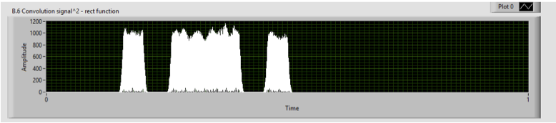
The figure below shows the morse signal after step 2 (i.e., filtering and detection).
Morse signal after filtering and detection of dots and dashes
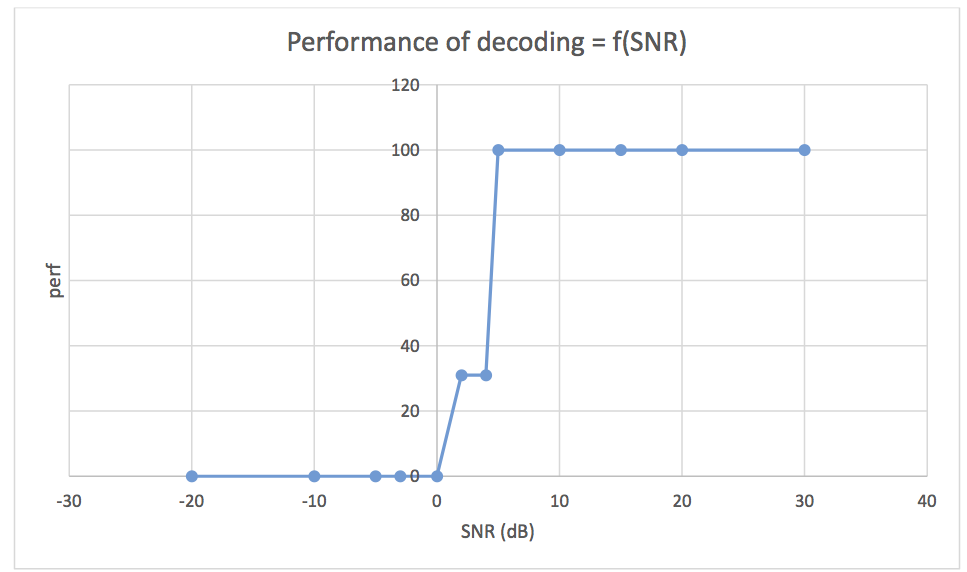
Alexandre also evaluated how his morse decoder performs when facing noisy signals. The performance is defined as the ratio of signs (letters, figures) that are correctly decoded (knowing what the original message should be). And here are the results:
Ratio of signs correctly decoded as a function of the signal to noise ratio
He’s been using LabView which makes his work a good candidate to be integrated in our LEO satellite ground station.
Nice work, Alexandre !
(and thanks to Marine C., professor at Telecom ParisTech who co-supervised the project).
HTS stands for high-throughput satellite. (Almost) everybody knows that. But what is behind the scene exactly ? Lorenz G., one of our former student points us to this interesting tutorial from Intelsat.
Learn about the Ka-band, multi-spot beam systems and frequency reuse. Besides, you’ll also signifcantly enhance your private collection of space related acronyms !
Since the launch of this web site, we received a lot of support from our former students through the LinkedIn Alumni group. So I wanted to say “Thank you” on behalf of the academic staff here, it is much appreciated. We’ll get you posted with more articles as the project #1 season is nearing to its end. We’ll have interesting topics to talk about.
Another “Thank you” to Yannick D. (through Tetraneutral.net) and Mercator Ocean who donated some hardware for our lab. A helpful hand, indeed.
To conclude, let us wish you all a happy Christmas break.
Software Defined Radio (SDR for short) is a new approach to design and deploy communication systems. It basically boils down to implement in software functions that are commonly found on ASICs (Application Specific Integrated Circuit). This is made possibly thanks for the ever-growing power of today’s CPU and also to the increasing popularity of FPGA (Field Programmable Gate Arrays).
In the SCS Programme, we believe that SDR is an important technology for space communications. Our experimental lab is equipped with cutting edge SDR technology such as the Vector Signal Transceiver from National Instruments. Another example is our “all digital” low earth orbit satellite Earth station that has been designed by students and faculty staff. Thanks to its SDR-based weather receiver, we observe in real-time weather conditions when NOAA POES satellites such as NOAA-18 fly over Europe.
So yes, in SDR we trust !
NOAA18 flying over Europe (southbound) on the 19th of September, 2013. Reception, demodulation and image decoding done on a NI USRP 2920 + LabView. Still some margin for improvement on the decoding side.
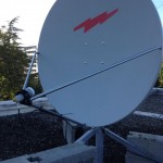
Step 1 went fine with all the mechanical aspects and the antenna mounting. Now, time for some pointing activities !
The method we relied on mixes an empirical approach and some measurements. It does not require you to know your exact location as long as you are in the Northern hemisphere. Here is the hardware we used :
Unloosing the bolts to adjust the azimuth
A wrench
A TV screen
A DVB-S demodulator for TV broadcast
A spectrum analyzer
A two-way radio system (PMR446)
The team was also split in two groups : one person on the roof and the rest in front of the analyzer. By now, you may guess what the PMR446 is for.
And here is the method we used :
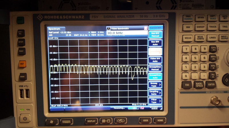
Hotbird 6 (13° E) carriers making the show on the spectrum analyzer
Point the antenna roughly southwards, elevation “flat”
Set the analyzer to “listen” to the LNB output on the L-band (say between 950 and 1250 MHz)
Start slowly increasing the antenna elevation
Check the analyzer screen for carriers to appear
Keep increasing the elevation until the carriers power starts fading away (1)
Decrease slightly the elevation to get back to the optimal elevation
Do the same for the azimuth : turn eastwards or westwards to maximize the power received from the carriers
Now you are pointing to a satellite … but which one ? This is where the DVB-S tuner comes into play. Look for the TV channels that are available on the received satellite and check against a satellite TV programme on the Internet … guessing what is the received satellite should be pretty easy.
One you know where you are, it is simple to hop from one satellite to another (2), eventually reaching you target. Finish by adjusting again the elevation and the LNB tilt and … voilà !
Note (1) : you may want to inccrease the elevation further to make sure you did not hit a secondary lobe.
Note (2) : using a compass might help you to initially start closer to the target satellite. Careful adjustement is required considering that our 1.2 m dish features a 3 dB aperture of 1.5° on the Ku band.
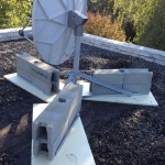
New students, new projects. This time, we are setting up a Ku band RX antenna to support two students involvded in channel measurements for their project 1. Time for some ODU (Out Door Unit) installation. Well, we have this 1.2 m dish sleeping in a corner of the lab, sounds like a perfect opportunity.
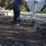
Removing the pebbles before laying the pads
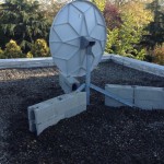
The first step is to get the antenna and the non penetrating mount on the lab roof. Easy. And then the 240 kg ballast. A little bit tougher.
Then comes the real thing with the removal of all the pebbles so to lay the antenna pads. Without these pads, the combination of pebbles and ballast will eventually compromise the roof waterproofing.
Putting back everything in place (pads, antenna, ballast and pebbles), now it is time to assemble the LNB. A universal Ku band LNB with 10.70 to 12.75 GHz coverage. The spectrum is split in two bands that are selected by injecting a 22 KHz tone in the cable. The polarization is controlled through the input voltage: 13 V for V pol. and 18 V for H pol. Now we’re ready for pointing … but that’s another story.