Category Archives: Student projects

Clouds across the Moon

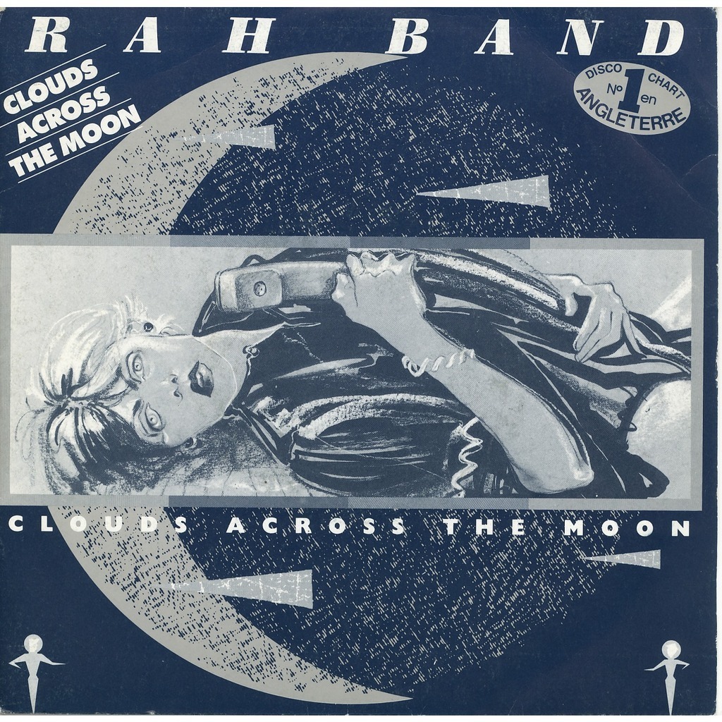
You certainly remember this song from the 80’s (but do you ?) featured by RAH Band.

For your recollection, here is the lyrics plot: a wife calls her husband who is on space mission close to Mars. The voice call goes through a deep space link which – this is lovingly old fashioned – is established by an “intergalactic operator”. After a couple of chit-chat, because of “violent storm conditions in the asteroid belt” the voice call is shut down. End of the story.

RAH Band's single "Clouds across the Moon"
RAH Band’s single “Clouds across the Moon”


Assuming that we are referring to a Voice over IP link, “Clouds across the Moon”  raises an interesting point. How robust are these space VoIP communications when faced with fading, jitter and other impairments ? This is precisely the problem that Alexandre V. and Gaëtan F. have been tackling during project #3 “Applications & services”.

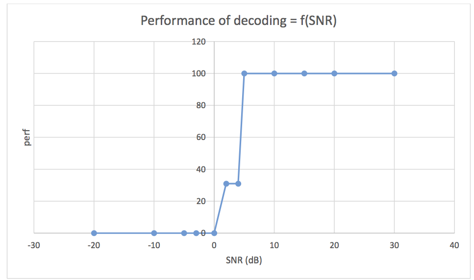
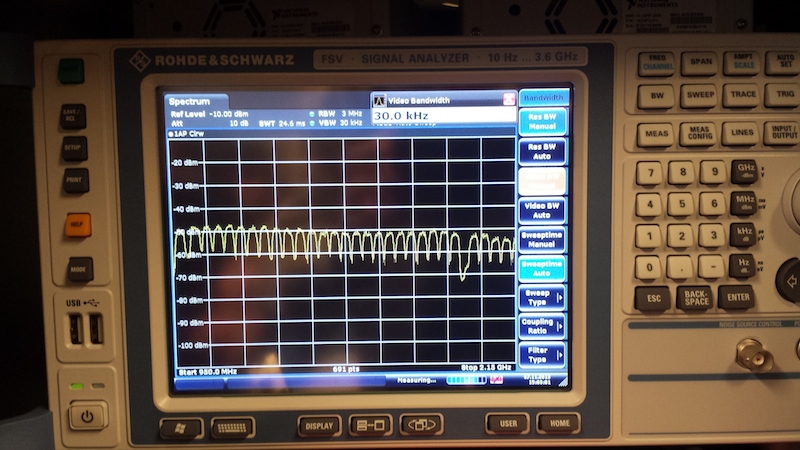
They set up a complete VoIP system with PABX and IP phones, fed the resulting trafic in our satellite channel emulator and did quite an extensive study about qualitative and quantitative performance.

Everything is summarised in their e-report.  It is certainly worth reading it, as their work is simply awesome.

Making the weather better

We already told you : we love to check the weather from a satellite perspective. Justine S. and Pierre L. (currently enrolled with the SCS programme) are working on how to improve the processing the weather images. So far, they achieved quite nice results.

Here is what we had before, with our plain and rustic processing:

Florida, plain image processing

And here is the same Florida after some enhanced processing (we’ll speak about what sort of enhancements in a later post):

Florida, with enhanced processing

At first glance, the original picture may seem to deliver a better contrast, but look at the details: line synchronization and noise within the image. The improvement is striking. They even took a (somewhat wild) walk on the color processing side:

Florida, fake colors

But that’s a different (psychedelic) story …


Monitoring the health of satellites

All satellites are made equal. At least regarding one point: the need to send  information about their health (the so called telemetry, TM for short).

During his project #1 (see our programme), Alexandre V. devised a morse decoder. But … hey …   wait … what is the relation between morse code and telemetry ? Well, some small satellites (e.g., cubesats) send telemetry information encoded in morse.

The method he implemented is a four step approach:

  1. Filter the audio signal so to isolate relevent frequencies
  2. Detect power peaks to spot dash and dots
  3. Characterize the alphabet by measuring spaces between (morse) words and letters
  4. Decode the message

The figure below shows the morse signal after step 2 (i.e., filtering and detection).

Morse signal after filtering and detection of dots and dashes

Alexandre also evaluated how his morse decoder performs when facing noisy signals. The performance is defined as the ratio of signs (letters, figures) that are correctly decoded (knowing what the original message should be). And here are the results:

Ratio of signs correctly decoded as a function of the signal to noise ratio

He’s been using LabView which makes his work a good candidate to be integrated in our LEO satellite ground station.

Nice work, Alexandre !

(and thanks to Marine C., professor at Telecom ParisTech who co-supervised the project).

Ku band RX experiment: step 2

Step 1 went fine with all the mechanical aspects and the antenna mounting. Now, time for some pointing activities !

The method we relied on mixes an empirical approach and some measurements. It does not require you to know your exact location as long as you are in the Northern hemisphere. Here is the hardware we used :

Unloosing the bolts to adjust the azimuth
  • A wrench
  • A TV screen
  • A DVB-S demodulator for TV broadcast
  • A spectrum analyzer
  • A two-way radio system (PMR446)

The team was also split in two groups : one person on the roof and the rest in front of the analyzer. By now, you may guess what the PMR446 is for.

And here is the method we used :

Carriers on the spectrum analyzer
Hotbird  6 (13° E) carriers making the show on the spectrum analyzer
  1. Point the antenna roughly southwards, elevation “flat”
  2. Set the analyzer to “listen” to the LNB output on the L-band (say between 950 and 1250 MHz)
  3. Start slowly increasing the antenna elevation
  4. Check the analyzer screen for carriers to appear
  5. Keep increasing the elevation until the carriers power starts fading away (1)
  6. Decrease slightly the elevation to get back to the optimal elevation
  7. Do the same for the azimuth : turn eastwards or westwards to maximize the power received from the carriers

Now you are pointing to a satellite … but which one ? This is where the DVB-S tuner comes into play. Look for the TV channels that are available on the received satellite and check against a satellite TV programme on the Internet … guessing what is the received satellite should be pretty easy.

One you know where you are, it is simple to hop from one satellite to another (2), eventually reaching you target. Finish by adjusting again the elevation and the LNB tilt and … voilà !

Note (1) : you may want to inccrease the elevation further to make sure you did not hit a secondary lobe.

Note (2) : using a compass might help you to initially start closer to the target satellite. Careful adjustement is required considering that our 1.2 m dish features a 3 dB aperture of 1.5° on the Ku band.

Ku band RX experiment: step 1

New students, new projects. This time, we are setting up a Ku band RX antenna  to support two students involvded in channel measurements for their project 1. Time for some ODU (Out Door Unit) installation. Well, we have this 1.2 m dish sleeping in a corner of the lab, sounds like a perfect opportunity.

Removing the gravel
Removing the pebbles before laying the pads

The first step is to get the antenna and the non penetrating mount on the lab roof. Easy. And then the 240 kg ballast. A little bit tougher.

Then comes the real thing with the removal of all the pebbles so to lay the antenna pads. Without these pads, the combination of pebbles and ballast will eventually compromise the roof waterproofing.

Putting back everything in place (pads, antenna, ballast and pebbles), now it is time to assemble the LNB. A universal   Ku band LNB with 10.70 to 12.75 GHz coverage. The spectrum is split in two bands that are selected by injecting a 22 KHz tone in the cable. The polarization is controlled through the input voltage: 13 V for V pol. and 18 V for H pol. Now we’re ready for pointing … but that’s another story.